|
|
|
|
Equipment
and Controls
|
|
|
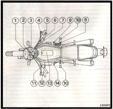
Control Location
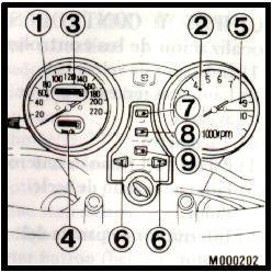
1. Speedometer Instruments and Indicator Lights
The instruments are grouped together above the headlight case. The indicator lights are located in the handlebar upper holders. 1. Speedometer Tachometer
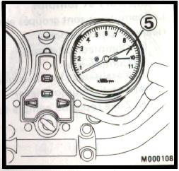
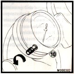
Red Zone During acceleration, engine RPM indicator needle may be allowed to enter the red zone briefly. However, the motorcycle must not be operated in the red zone (5) for any length of time and must NEVER be operated beyond it. Tripmeter
Use the tripmeter to calculate mileage on trips. Reset to zero with the knob (10). Ignition Switch
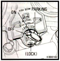
The ignition switch is located directly below the indicator panel. OFF: All electric circuits open. Engine cannot be started. Key can be removed. ON: All electric circuits close. Engine and lights can be operated. Key cannot be removed. LOCK (STEERING LOCK): General type only. (See STEERING LOCK) Headlight Switch
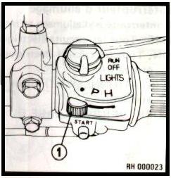
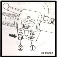
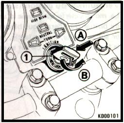
The headlight switch (1) has three positions; "H","P" and "OFF" marked by a red dot to the left of "P". H: Headlight, taillight, position light and meter lights on. P: Position light, taillight and meter lights on. OFF (red dot): Headlight, taillight, position light and meter lights off. Starter Button / Engine Stop Switch
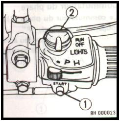
The starter button (1) will operate the starting motor. When you press in the button, the starter cranks the engine. The use of this button is explained under "STARTING THE ENGINE". Your motorcycle is equipped with an engine stop switch (2). In the "OFF" position, the ignition circuit is open. The switch should normally be placed in the "RUN" position. Do not use this switch except to stop the engine in an emergency. Turn Signal Switch
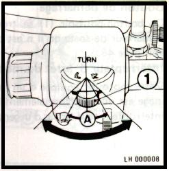
To signal a left turn, move the switch (1) to the "L" position. To signal a right turn, move the switch (1) to the "R" position. When the switch is moved within range (A), the turn signal flashes until the switch is released, then the switch returns to the centre off position. Moving the switch beyond this range, the turn signal flashes and warning buzzer sounds until the switch is moved to the centre off position. Headlight Dimmer Switch Horn Passing Light Control Switch
Turn the headlight dimmer switch (1) to "Lo" for low beam, and "Hi" for high beam. When the switch (2) is pressed, the horn sounds. When it is pressed in the direction of the arrow, the headlight flashes on to signal approaching cars or when passing. Seat Lock and Helmet Holders
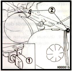
The ignition key unlocks the seat lock (1) on the lower right side of the seat. To unlock, insert the ignition key and turn it 90° to the left. The helmet holders (2) are located under the seat. WARNING: The helmet holder is designed for helmet security while parking. Do not operate the motorcycle with a helmet attached to the holder. Document Compartment
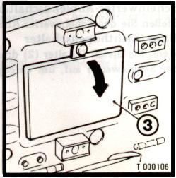
Your motorcycle is equipped with a document compartment (3) under the seat. Steering Lock (Except General Type)
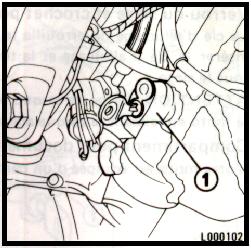
The motorcycle has a steering lock (1) on the steering column under the headlight case. To lock the steering, turn the handlebar all the way to the right insert the steering key in the lock, turn the key 60° to the left, and press the lock all the way in. Turn the key back to the original position and remove. To unlock the steering, perform the locking sequence in the reverse order.
The steering can be locked when the ignition switch (1) is in "LOCK" position. Turn the handlebar all the way to the steering stop, either to the left or right, insert the key at the "OFF" position, turn it counterclockwise to "LOCK" position while pushing it in and then remove the key. To unlock, only turn the key clockwise. Rear Shock Absorbers
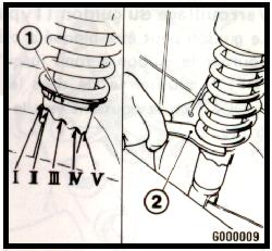
Each rear shock absorber (1) has five adjustment positions for different types of road or riding conditions. Position III is the standard setting. Position I is for light loads and smooth road conditions. Positions II to V progressively increase spring tension for a stiffer rear suspension, and are used when the motorcycle is more heavily laden or operated on rough roads. Adjustment is made with the pin spanner.
|